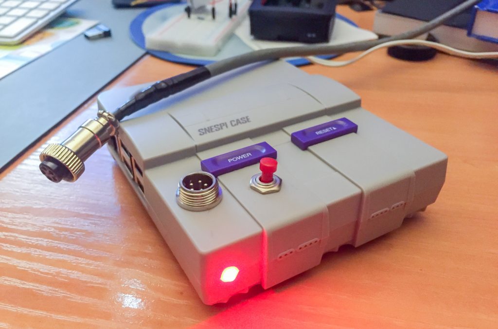

This article describes the development of a pulse dialing telephone reader and audio sample player (poems – each digit a poem). A challenge proposed to me by Carlos Moura-Carvalho, author, for an artistic installation in three commercial establishments of cultural concept in Lisbon.
Decadic signalling was used to send information – numerical data, or more simply binary code – from the telephone to the automatic telephone exchanges.
Originally this signalling is generated by a “disk” which opens and closes the circuit periodically generating a series of pulses according to the number selected on the telephone disk.

This was telephone technology in my youth, which increased my enthusiasm to embrace the project.
FIRST STUDY:
Besides knowing these phones systems from a young age, the idea of a pulse reader-interpreter didn’t seem difficult to me to get through using a microprocessor like Arduino or Raspberry Pi. Coding counting loops of change-of-state in the raspberry ports, a simple binary job. On the other hand, when studying the matter depply, I reminded that these devices were powered by electric current through the line, between 2.5V and 5.5V, values very close to those used by Arduino and Raspberry controllers, however there’s capacitors on the circuit to generate 250V peaks to trigger the bells. Yes, I could set some diodes but put it simple and avoid risks, and since I had no purpose of ringing the phone bells, I choose to make use of the internal connectors, to obtain the simple analog pulses of interruption/continuity, we should say, in a passive mode. This way have discarded the possibility of using the internal circuit and only use the mechanics of the pulsing dial.

pulse ports and bell 
electronic scheeme founded inside 
test chart
After squeezing the circuit, and measured resistance values at various ports, it turned out that changing the connections at the output ports would have what I needed: Sending the pulses to Pi and returning the sound to the phone headset via a single cable. Therefore I’ll be needing 4 wires. So I chose CAT6 network cable (6 wires), the required was short length so interference isolation is dispensable.
HARDWARE:
- Pulse Reader port
- Headphone port (I wanted internal connections, no external cables, so I soldered contacts on the 3.5mm TRS case conductors of the analog audio jack)
- Power supply for fan
- Port for status LED
- Port for shutdown switch (to shut down the system daily without flash memory problems)
I added a small resistance of 10KΩ to the pulse reader port to ensure that the open state value was practically infinite.
The fact that there are no internal connections to analog audio made me suggest to the Raspberry community to include this feature in a next update. It would be very welcome for users and would be very simple to incorporate, almost at no additional cost.
The cooling fan came with the SNESPI Raspberry case which ensures peace of mind to operate during the summer. The current consumption increase is very small (100mA). As such I opted for direct connection, without setting any speed/temperature controller.
Switching off the system could create problems, because Raspberry doesn’t have a switch, the project doesn’t include a screen or access interfaces and the power cut could happen when some flow to the SD card takes place leading to the loss of information. It have already happened in a video-art installation, fortunately I was close by and was able to quickly replace the system SD with the backup one. So based on this project and added a Shutdown button that triggers a system shutdown routine and turns off all the software befora power off.
We are warned by an LED, which goes off when it shuts down, and we’ll know when to turn off the power. It was based on this other project with a few minor changes.

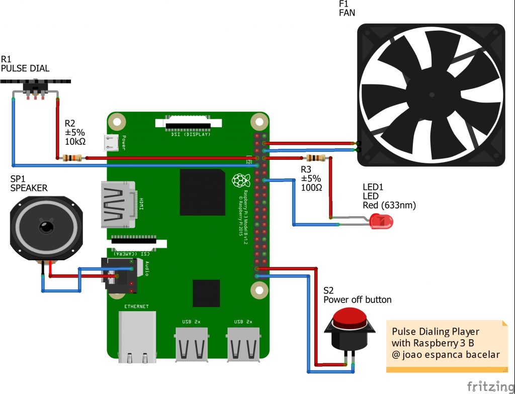
electronic circuit 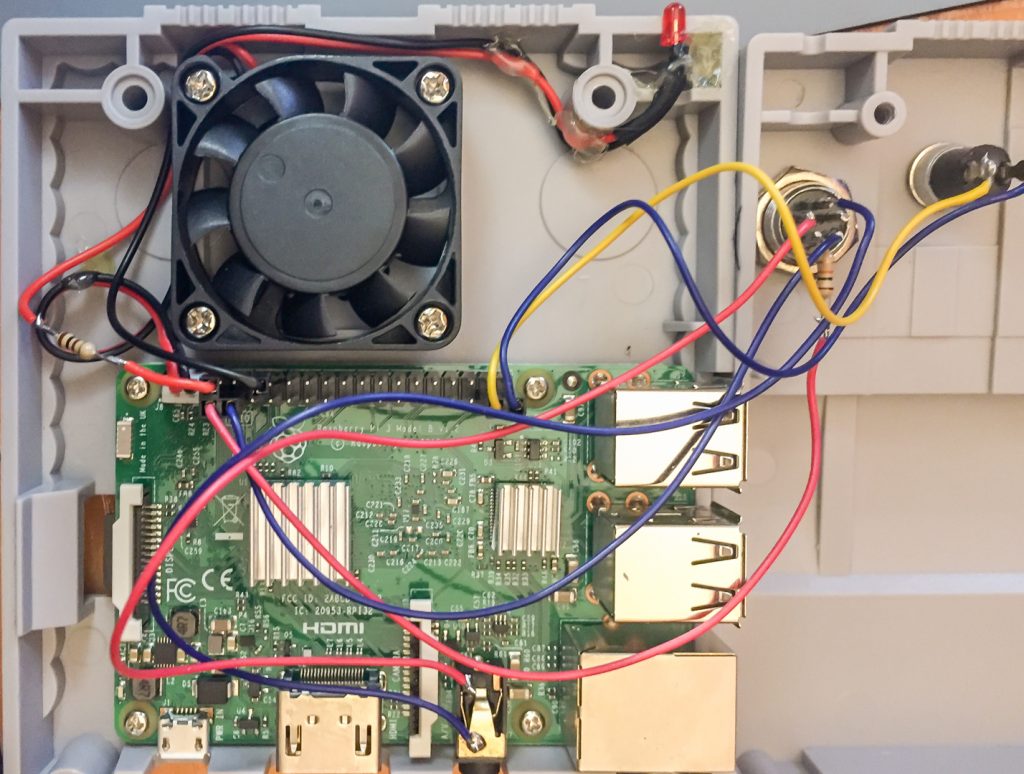
Assembly
_________________
The second step was aimed at creating the software for communication with the Raspberry (3B) ports, for which the following issues had to be resolved:
SOFTWARE:
- Pulse and sample player program.
- Start the pulse player with an auto-run right after starting the operating system.
- Allow the use of a USB stick for later modification of the audio samples.
- Routine shutdown button and warning LED.
The operating system I used was the Raspbian (2019-04-08-raspbian-stretch), I have more Raspbian configuration details in this article: Raspberry Pi Tips.
I could have used the Raspbian version without visual interface, lighter but anyway I only configured graphics in the initial phase to get feedback as I debugged the code. From this I eliminated the whole graphics process within the sketch.
The pulse counter program was done in Processing because I’m more comfortable with the language (Java / C / C++) and had to be built practically from scratch. I found few examples of routines that solved the counting cycles issue. I needed several steps to confirm the gestures made by the user just by reading the pulses, that is:
- standby 1 (OFF mode);
- Lift the handset;
- Issue presence signal;
- Wait 2 (ON mode);
- Mark a series of pulses;
- Check that the series has ended;
- Use the last value of the series to trigger the respective sample;
- Restart the wait 2. or
- Close – start waiting 1.
I’m posting the code forward with comments so not going into detail here but I’ll mention a few points from solving the pulse-counting issue using loops:
The first loop checks whether the handset is on rest or a pulse is happening (GPIO.HIGH).
If it is confirmed, it increases the off_time variable and restarts the on_time variable.
At second loop checks if off_time is greater than 20 (value I calculated to be above the time range between dialer pulses):
- if yes, assumes the phone was hunged up, pauses the presence tone and resets the flag, count and off_time variables;
- if it is not greater than 20 and the flag is equal to 0, increases the number of count and the flag goes to 1 (true) .
if (GPIO.digitalRead(4) == GPIO.HIGH) {
off_time++;
on_time = 0;

if (off_time >= 20) { // more than 20: DOWN

  if (playertone.isPlaying()) {
    playertone.pause();
  }
  flag = 0;
  count = 0;
  off_time = 20; // stop adding numbers
}

if (off_time < 20) { // less then 20: COUNT
  if (flag == 0) {
    count ++;
    flag = 1;
  }
}
}
If the headset is up (GPIO.LOW), then it passes the off_time variable and flag to false. It checks if the time between on and off was greater than 20 and passes the count value to the variable that will choose the audio sample to play switchPoema.
if (GPIO.digitalRead(4) == GPIO.LOW) {
      off_time = 0;
      flag = 0;
      }
 if (on_time > 20) {
      on_time = 0;
      }
    on_time++;

    if (on_time > 10) {
      switchPoema = count;
      count = 0;
    }
The remaining code can be seen in the file itself and there’s comments in it. I leave here the summary and attachments:
Supplies:
- Analog Pulse Telephone
- Raspberry Pi 3B micro processor + power
- LED up to 5V
- Resistance 10kΩ
- Resistance 100Ω
- Push button (normally open)
- SNESPI box for Raspberry
- CAT6 network cable (1.5m)
- Multi-wire cable 0.5mm
- 4-pin connectors (M and F)
- 7 NSR female plugs
- 7 NSR terminals
- Welding, etc…
Code:
Sketch Processing: Pulse-dialing-player.pde